Injuries due to failure of divers emergency gas cylinder – use of incompatible threads
An International Association of Oil & Gas Producers (IOGP) member has passed to IMCA for circulation to members an incident in which a pillar valve forcefully parted from a High Pressure (HP) cylinder filled with 180 bar of compressed air. The incident occurred on board a DSV (Diving Support Vessel) whilst divers prepared for a dive and were putting on their diving suits. As a result of the failure, five divers were injured as the parted valve flew off the cylinder.
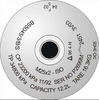
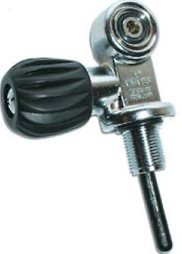
A pillar valve or cylinder valve is the point at which the cylinder connects to the diving regulator. The purpose of the pillar valve is to control gas flow to and from the cylinder. The neck of the cylinder is internally threaded to fit a cylinder valve. Parallel threads are made to several standards and the most common standards are:
- M25x2 parallel thread, sealed by an O-ring;
- M18x1.5 parallel thread, sealed by an O-ring;
- 3/4″x14 BSP parallel thread, with a 55° Whitworth thread form;
- 3/4″x14 NGS (NPSM) parallel thread, sealed by an O-ring;
- 3/4″x16 UNF, sealed by an O-ring.
All these parallel threads are very similar but not compatible, as pitch, pitch diameter and thread forms are different.
The following points were noted:
- Investigation is still ongoing but preliminary assessment has confirmed that the inner thread on the HP cylinder was not compatible with the outer thread of the pillar valve;
- The HP gas cylinder inner thread was an M25x2 parallel thread, and the outer thread on the pillar valve was a 3/4″x14 BSP parallel thread (Whitworth);
- How the incompatible valve and HP gas cylinders came to be used together is still being investigated.
The following lessons were learnt:
The incompatibility of the valve thread and HP cylinder thread led to a serious incident. It is therefore of great importance that all diving contractors perform an immediate check to confirm the compatibility of the HP gas cylinders and valve threads in use at their operations. They should also clearly mark and register both HP gas cylinders and valves separately, so that compatibility can be verified and assured.


The following actions were suggested:
- Check HP gas cylinder threads and pillar valve threads for compatibility, ensuring that auditable evidence is made available;
- Mark the cylinder thread size for all HP cylinders – mark the thread size for all pillar valves, applying a unique identification that will be permanently visible and traceable;
- Have a working procedure and instruction in place that includes the verification of the compatibility of both the pillar valves and HP gas cylinders;
- Include compliance with this working procedure in the DESIGN audits which validate the 6 monthly internal and external inspections of HP gas cylinders;
- Include the HP gas cylinder and pillar valve identification numbers in the 6 monthly inspection certificates.
Members may wish to refer to the following incidents (search words: pillar):
Safety Event
Published: 7 January 2016
Download: IMCA SF 01/16
IMCA Safety Flashes
Submit a Report
IMCA Safety Flashes summarise key safety matters and incidents, allowing lessons to be more easily learnt for the benefit of all. The effectiveness of the IMCA Safety Flash system depends on Members sharing information and so avoiding repeat incidents. Please consider adding safetyreports@imca-int.com to your internal distribution list for safety alerts or manually submitting information on incidents you consider may be relevant. All information is anonymised or sanitised, as appropriate.
IMCA’s store terms and conditions (https://www.imca-int.com/legal-notices/terms/) apply to all downloads from IMCA’s website, including this document.
IMCA makes every effort to ensure the accuracy and reliability of the data contained in the documents it publishes, but IMCA shall not be liable for any guidance and/or recommendation and/or statement herein contained. The information contained in this document does not fulfil or replace any individual’s or Member's legal, regulatory or other duties or obligations in respect of their operations. Individuals and Members remain solely responsible for the safe, lawful and proper conduct of their operations.
