Fatality during anchor handling operation
A member has reported a fatal incident which occurred during anchor handling operations. The incident occurred on an anchor handling tug (AHT) whilst crew were attempting to disconnect an anchor buoy (weighing 1.4 tons) from its pennant wire shortly after retrieval.
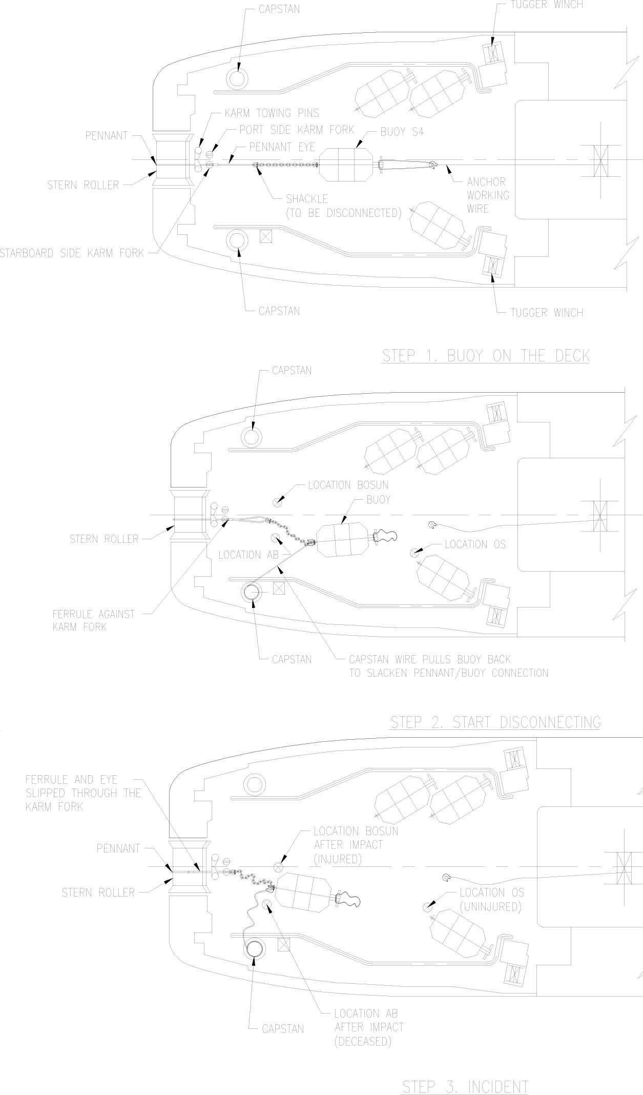
The anchor buoy was winched onto the deck of the AHT until the pennant was in the wire stopper used to prevent the buoy from being pulled back towards the stern by sudden tension on the pennant wire. (See Fig. 1 Step 1.) Two crew members were disconnecting a shackle between the pennant wire connected to an anchor on the seabed and the buoy on deck (See Fig.1 Step 2), when suddenly the pennant wire came under tension. The wire stopper failed to stop the pennant wire effectively and the sudden tension on the pennant wire jerked the buoy towards the stern of the vessel. The two crew members who were busy disconnecting the shackle where struck by the moving buoy. (See Fig. 1 Step 3). One crew member died instantly, the other suffered a minor injury.
Root cause
Our member conducted an investigation and the root cause of the incident was determined to be that the wire stopper failed to stop the pennant wire. This happened because an incorrect (oversized with respect to the diameter of the pennant wire) ‘U-shaped insert’ was mounted into the wire stopper. This ‘U-shaped insert’ also displayed excessive wear and tear. (See Figures 3 & 4) As a consequence of this the socket at the end of the pennant was able to pass through the wire stopper when the pennant wire came under tension.
The sudden tension on the pennant wire came about because the survey screen on the bridge of the AHT displayed a ‘design anchor position’ instead of the ‘as laid’ anchor position. Based on the information presented by the survey screen, it was assumed that there was sailing slack in the pennant wire when in fact, it was being tensioned. (See Figure 2)
Recommendations and corrective actions
Our member made the following recommendations and corrective actions:
- A thorough check of the wire stopper’s exchangeable parts should be made to ensure that it is adequate to handle the actual pennant wire diameter, and this should be recorded
- A monthly inspection and check on wear and tear of the wire stopper equipment should be added to the vessel’s planned maintenance system
- The ‘as laid’ information of the anchor should be provided by the positioning subcontractor and displayed on the survey screen
- The survey screen provided by the positioning subcontractor should be considered an additional tool to provide an assumed anchor location to the AHT, but this location should never be interpreted as representing the actual anchor position. A warning message to this effect should be displayed on the survey screen
- A dedicated watch should be maintained throughout the operation of buoy recovery on the direction and tension of the pennant wire.


Safety Event
Published: 8 April 2010
Download: IMCA SF 02/10
IMCA Safety Flashes
Submit a Report
IMCA Safety Flashes summarise key safety matters and incidents, allowing lessons to be more easily learnt for the benefit of all. The effectiveness of the IMCA Safety Flash system depends on Members sharing information and so avoiding repeat incidents. Please consider adding safetyreports@imca-int.com to your internal distribution list for safety alerts or manually submitting information on incidents you consider may be relevant. All information is anonymised or sanitised, as appropriate.
IMCA’s store terms and conditions (https://www.imca-int.com/legal-notices/terms/) apply to all downloads from IMCA’s website, including this document.
IMCA makes every effort to ensure the accuracy and reliability of the data contained in the documents it publishes, but IMCA shall not be liable for any guidance and/or recommendation and/or statement herein contained. The information contained in this document does not fulfil or replace any individual’s or Member's legal, regulatory or other duties or obligations in respect of their operations. Individuals and Members remain solely responsible for the safe, lawful and proper conduct of their operations.
